The first attempt at fabrication ran into kerfing problems. Maker case appeared to ask for the laser's radius, while my notes on the laser gave the laser's kerfing as its diameter. I did not notice that maker case was asking for the radius instead of the diameter, so my kerfing was set to be too large. As a result, the fit was too tight to assemble the box.
The settings used for cutting my 0.093" piece of acrylic were:
These settings seemed to leave a few too many attached pieces, so I adjusted them slightly on the next pass.
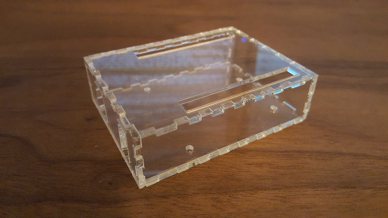
The second fabrication attempt fared better. Having redone the design (see the previous assignment for the final version) the finger joints fit together very well. However, the next problem soon became apparent: although the board fit in the case, and the pins and ports were accessible, the holes on the bottom for the mounting screws seemed to be sized as if for a smaller board. Upon reflection, I had given some generous margins to the case, yet the case that was printed was of a somewhat closer fit. I thus suspected that the case had been scaled down from the original design.
To test this hypothesis I measured the distance between the two mounting holes towards the back of the Arduino and, very roughly speaking, found them to be 4.7cm apart. This measurement was in accordance with the two unofficial specifications I had been working off of. I then measured my case, and the equivalent mounting holes were roughly 4.5cm apart. To see whether the error had been in the initial vector graphic or the process of transferring it to the printer, I used InkScape's ruler tool to measure the same span on the drawing. My InkScape drawing had the correct distance of roughly 4.7cm, so I was able to narrow that down as the source of error.
The settings used for cutting my 0.093" piece of acrylic were:
Specifically I reduced the speed by 1%. This seemed to make cleaner cuts, so I kept these settings for the rest of the lab.
At this point I had remembered a reminder in lecture about setting the print scaling, that I had somehow overlooked in the notes. The value that had been left in the dialogue was very roughly 93%, whereas the value from class was about 94%. I knew this wasn't enough to account for the difference in scaling mathematically, but I was curious to see what difference it made, so I ran it with the corrected print scaling factor. No difference was visible.
At this point I had hypothesized that setting the scaling to 100% may resovle the problem. Sure enough, 4.5 x 100 / 94 = 4.78, and the actual scaling factor was greater than 94%. Given that my measurements were not into the 5mm level of accuracy this seemed to me a reasonable hypothesis. Plus intuitively, having set the correct dimensions in my vector graphics, I did not want the printing to apply any scaling to alter those dimensions.
Despite all my reasoning, the cut case was the exact same dimension as the previous one. Whereas before I had chalked up the similarity to the very similar scale factors, this run made it clear that the print scaling setting was not being applied at all.
Unfortunately, I did not have the opportunity to try another solution, as I wanted to make sure everyone else had a chance to use the laser cutter. Nevertheless, at the end of the session I still had a pair of cases for the Arduino Uno that would be functional in situations without a lot of movement, and would be entirely functional with only a small amount of modification - I could drill the mounting holes in the correct position without much difficulty. However, I would prefer to wait until my own Arduino comes in the mail before doing that, so I can mark the locations directly on the case with a sharpie and be certain that I'm drilling in the right place.
As far as the specific scaling problem I was encountering, my impression is that ATX Hackerspace has a good summary of the problem I was facing in their section "Exporting to SVG". Namely, the PPI ratio between CorelDraw, which the Epilog laser cutter expects to be used, to Inkscape is 96/90. That site recommends simply scaling the entire graphic 106.667% not in the print settings, but at the actual vector drawing level before printing, to account for the difference. This would have put my mounting holes 4.8 mm apart, which seems slightly wider than measured but could be within my measurement's precision. It is unfortunate that the print settings themselves cannot account for these differences and standardize by real-world distance units such as inches or mm.
This session has illustrated the importance of familiarity with the manufacturing tools and software. More research between cuts could have potentially saved me a fair amount of time and led to superior results. Another possible improvement in the procedure could have been to somehow measure the distances between the mounting holes during the dry run. Filming the dry run from the top down would have let me "measure twice, cut once" as far as the manufacturing procedure was concerned.